

Manual - Hydraulic Steering System
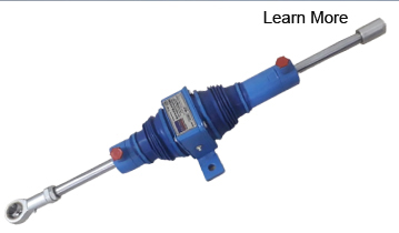
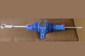
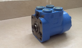
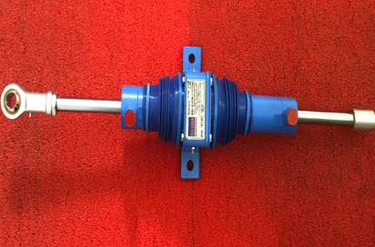
Balanced Hydraulic Actuator-Model:BHIMA
For Passenger Boat, 75-200 PAX,House boats, Light Barges.
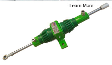
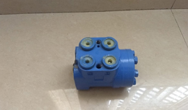
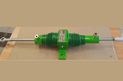
Balanced Hydraulic Actuator-Model:CETO
For Passenger Boat, 10-25 PAX,Survey vessels, Ambulance rescue Boat.
Balanced Hydraulic Actuator-Model:TUNA
For Medium Fishing Vessels-60.75 Feet,sea going survey vessels.
|
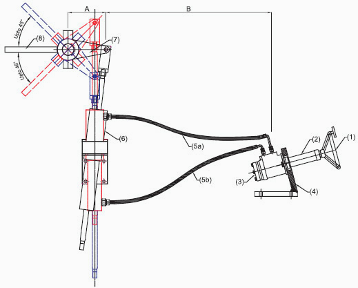
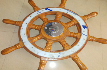
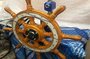
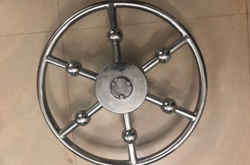
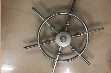
Schematic for BHIMA, CETO and TUNA. 1. Steering Wheel 2. Steering Column 3. Helm Pump 4. Helm Pump Bracket 5. 5b. Flexible Hoses 6. Hydraulic Actuator 7. Tiller Arm 8. Rudder Plate |
Water borne vessels, big or small, need navigation control to cruise through water and to move through a controlled path. As vessels move forward by pushing the water backward, the guidance of the vessel by turning it right or left can be controlled by directing the pushed water towards respective direction.
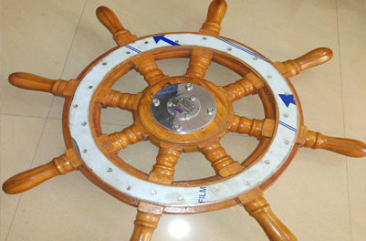
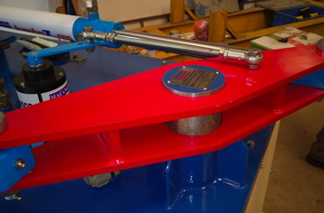
A plate of steel, connected to a rod, which is extended to a convenient height of the boat deck, is used to deflect water to both sides, according to the requirement of turning. This plate is called RUDDER PLATE and the shaft extending to the deck, connected to the rudder plate is called RUDDER- STOCK. The boat driver will use mechanical or Hydraulic systems to turn a rod connected to the rudder-stock to do the turning job. This rod, used to turn the rudder plate is called TILLER-ARM. Though control of Tiller-Arm is easy for small boats running slow in backwaters /lakes, it requires high effort and skill to hold tiller-arm in right position in sea, as well as during fast movement in backwaters.
As the fast-moving / heavy modern vessels use an engine to run a propeller, to push water backwards, they use modern mechanisms to guide the vessel. In these vessels, angular movement of rudder-plate is precisely and efficiently controlled by Hydraulic actuators, driven by closed-loop manual/diesel-run hydraulic systems.
Based on mounting position of the engine, vessels are classified into two. In-Board Vessel, with engine mounted inside the vessel, and Out-Board vessel with engine mounted outside the vessel, preferably backside of vessel.
COMPONENTS OF MANUAL - HYDRAULIC STEERING SYSTEMS
|
BALANCED HYDRAULIC LINEAR ACTUATOR A Balanced Hydraulic Linear Actuator is planned, to turn the Tiller-Arm to both sides of the vessel, smoothly and precisely. Oil supply ports are provided on both sides of this actuator, through which, oil can be supplied to the piston of the actuator. As pressurised oil is supplied from the Helm Pump to the Linear Actuator, the piston-rod will move forward or backward, depending on, to which supply port, oil is provided. The Pistonrod-end / Ram-end of this actuator has a flexible connector, which can be coupled to the Tiller-Arm. As the driver rotates the steering wheel to one side, oil filled in the circuit flows from one side of the circuit to the other side of the circuit, enabling the Pistonrod of Actuator to move from one side to the other. When the driver rotates in opposite direction, the same process will repeat resulting Pistonrod movement in the opposite direction. |
Balanced Hydraulic Actuator-Model:BHIMA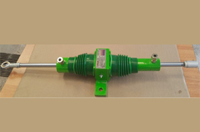
Balanced Hydraulic Actuator-Model:CETOThermo Plastic Hoses, as well as Zinc-coated Seamless Steel Tubes are recommended for transmission of oil from the Helm Pump to the Hydraulic Actuator. In small boats, Thermo Plastic hoses will be sufficient. But in longer vessels, Zinc-coated Seamless Steel tubes are recommended between Thermo Plastic hoses at the Helm Pump-end and Actuator-end. |
|
OIL FEEDING AND SELF - PRIMING SYSTEM To feed oil in the circuit, a Filler Breather is provided on top of a Reservoir Unit mounted on the Helm Pump. After filling oil in the Reservoir, drive-shaft of the Helm Pump is rotated in one direction by a Steering Wheel. Oil will flow to that side of the circuit and air trapped in the other side will escape through a special attachment in the Reservoir. On rotating the Steering Wheel to the other side, any air trapped in the first side will escape through the attachment. Two repeated efforts will make the full driving system ready for driving. An Oil Level Indicator is mounted on the Reservoir Unit for monitoring quantity of oil in the circuit In small boats, Thermo Plastic hoses will be sufficient. But in longer vessels, Zinc-coated Seamless Steel tubes are recommended between Thermo Plastic hoses at the Helm Pump-end and Actuator-end. |
| HELM PUMP The Helm Pump Assembly has built-in relief and check valves. Along with Pressure developing mechanism, a direction control valve also incorporated Thus it is very compact steering unit which reduces the need for additional hydraulic components in the system. Discharge 80 cc per revolution. |
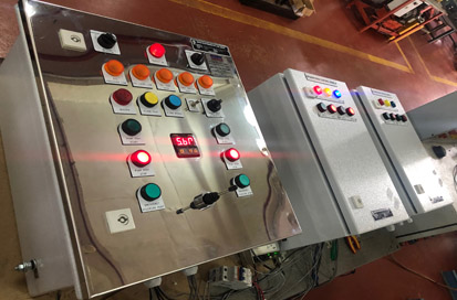
Electro - Hydraulic Steering Systems
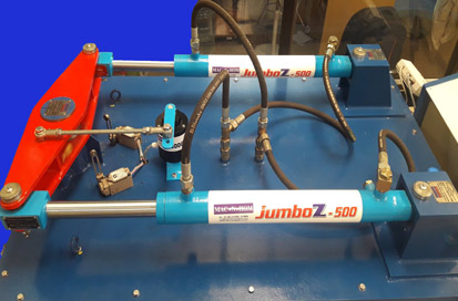
Hydraulic Steering system Model:
JumboZ- 500
For Heavy Fishing Vessels,100 Feet Medium Barger, High Speed Passenger Vessels.
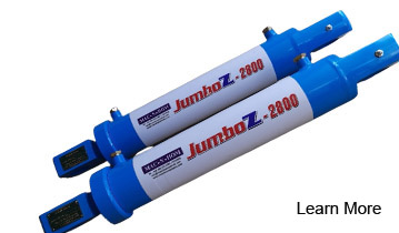
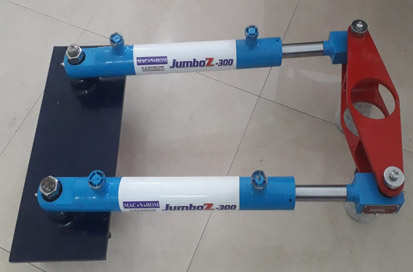
Hydraulic Steering system Model:
JumboZ-300
For Heavy Fishing Vessels,100 Feet Medium Barger, High Speed Passenger Vessels
| Our decades of experience in Hydraulic as well as Marine Systems proved that, |
|
DRIVE for our Power-Hydraulic Steering Systems are offered in TWO versions
-Electric Motor Driven Power-Hydraulic Steering System.
-Engine Driven Power-Hydraulic Steering System.
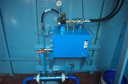
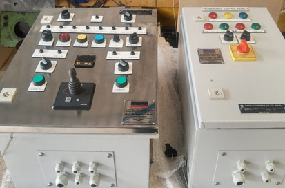
ELECTRIC MOTOR DRIVEN POWER-HYDRAULIC STEERING SYSTEM
Marine Vessels with Generator Power use Electric Motor driven Hydraulic Powerpacks to energise Power-Steering Systems. This hydraulic system can be controlled through Joy Stick or through Steering Wheel Driven Helm Pumps OR both.
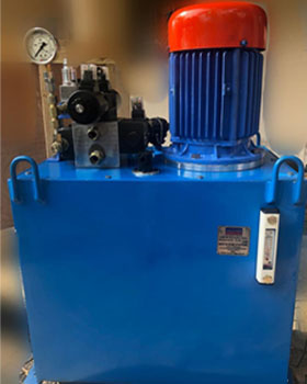
Single Motor Power Pack
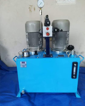
Twin Motor Power Pack


